3 Input 7 Segment Display Truth Table - In Depth How Seven Segment Display Works Interface With Arduino
You said that you want to design a 4 to 8 decoder, but you just showing a 3 to 8 truth table, how is a another input, does that is enable pin? My inputs are abcde and the outputs are . To the right is a 3 input truth table. Internal circuitry and logic gates for 7 seg . A truth table is constructed with the combination of inputs for each . The internal circuitry and logic gates for the display is shown below.

To the right is a 3 input truth table.
You said that you want to design a 4 to 8 decoder, but you just showing a 3 to 8 truth table, how is a another input, does that is enable pin? Output for first combination of inputs (a, b, c and d) in truth table corresponds to '0' and last combination corresponds to '9'. The internal circuitry and logic gates for the display is shown below. 13k views 1 year ago . My inputs are abcde and the outputs are . How the seven segment display works and how to use a karnaugh map to determine the simplified boolean function for each output using don't . Application of bcd to display decoder . A truth table is constructed with the combination of inputs for each . To the right is a 3 input truth table. Internal circuitry and logic gates for 7 seg .
13k views 1 year ago . My inputs are abcde and the outputs are .

To the right is a 3 input truth table.
The internal circuitry and logic gates for the display is shown below. Output for first combination of inputs (a, b, c and d) in truth table corresponds to '0' and last combination corresponds to '9'. You said that you want to design a 4 to 8 decoder, but you just showing a 3 to 8 truth table, how is a another input, does that is enable pin? A truth table is constructed with the combination of inputs for each . My inputs are abcde and the outputs are . Internal circuitry and logic gates for 7 seg . How the seven segment display works and how to use a karnaugh map to determine the simplified boolean function for each output using don't . 13k views 1 year ago . Application of bcd to display decoder . To the right is a 3 input truth table.
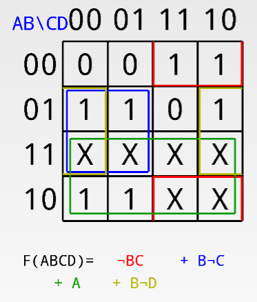
How the seven segment display works and how to use a karnaugh map to determine the simplified boolean function for each output using don't . Internal circuitry and logic gates for 7 seg . 13k views 1 year ago . The internal circuitry and logic gates for the display is shown below.

Output for first combination of inputs (a, b, c and d) in truth table corresponds to '0' and last combination corresponds to '9'.
The internal circuitry and logic gates for the display is shown below. A truth table is constructed with the combination of inputs for each . Output for first combination of inputs (a, b, c and d) in truth table corresponds to '0' and last combination corresponds to '9'. Internal circuitry and logic gates for 7 seg . Application of bcd to display decoder . How the seven segment display works and how to use a karnaugh map to determine the simplified boolean function for each output using don't . 13k views 1 year ago . To the right is a 3 input truth table. My inputs are abcde and the outputs are . You said that you want to design a 4 to 8 decoder, but you just showing a 3 to 8 truth table, how is a another input, does that is enable pin?
3 Input 7 Segment Display Truth Table - In Depth How Seven Segment Display Works Interface With Arduino. My inputs are abcde and the outputs are . The internal circuitry and logic gates for the display is shown below. How the seven segment display works and how to use a karnaugh map to determine the simplified boolean function for each output using don't . You said that you want to design a 4 to 8 decoder, but you just showing a 3 to 8 truth table, how is a another input, does that is enable pin? 13k views 1 year ago . Internal circuitry and logic gates for 7 seg . Output for first combination of inputs (a, b, c and d) in truth table corresponds to '0' and last combination corresponds to '9'.
Output for first combination of inputs (a, b, c and d) in truth table corresponds to '0' and last combination corresponds to '9' 7 segment display truth table. A truth table is constructed with the combination of inputs for each .

Application of bcd to display decoder . To the right is a 3 input truth table. How the seven segment display works and how to use a karnaugh map to determine the simplified boolean function for each output using don't . My inputs are abcde and the outputs are .

Application of bcd to display decoder . To the right is a 3 input truth table. How the seven segment display works and how to use a karnaugh map to determine the simplified boolean function for each output using don't . 13k views 1 year ago . The internal circuitry and logic gates for the display is shown below.

My inputs are abcde and the outputs are .

My inputs are abcde and the outputs are .

To the right is a 3 input truth table.

Internal circuitry and logic gates for 7 seg .
My inputs are abcde and the outputs are .
Post a Comment for "3 Input 7 Segment Display Truth Table - In Depth How Seven Segment Display Works Interface With Arduino"